


2023 - 2024
Iceberg ASV will be returning to the International RoboBoat competition for a second time in February 2024, to represent Newfoundland & Labrador and Canada as a whole. The team is actively working on iterative design and testing of this year’s ASV.

2023 - 2024 Blog:

RoboBoat 2024 Results!
March 2024

Iceberg ASV competed at the International RoboBoat Competition for the second time in 2024. The 2024 International RoboBoat Competition took place in Sarasota, Florida from February 4-11. Eighteen teams from around the globe gathered to compete with their autonomous surface vehicles. Fourteen of Iceberg ASV’s members were in attendance to compete with the autonomous surface vessel — Sonny's Dream.
The results are in:
9th Place Overall, 4th Place Design Documentation, 4th Place Presentation, 5th Place Website
Overall, the team worked amazingly together throughout the entire week by maintaining communication and good spirits. We have learned so much since last year's competition, and we are so proud of how far we have come.
As undergraduate students, it is rare to have the opportunity to collaboratively design and build a complete team and system from scratch. Building an autonomous boat has developed our technical skills and project management skills in an interdisciplinary setting. This project has given the whole team a new outlook on our coursework as team members have been able to apply concepts learned in class to a real-world challenge. Iceberg ASV intends to grow its team and scope in 2025 - from a complete re-design of the ASV to recruitment, the team has big plans for the year ahead!

Sonny’s Dream - Where Does The Name Come From?
January 2024
Meet Sonny’s Dream, Iceberg ASV’s vessel for the 2023 – 2024 competition season. Continuing Iceberg ASV’s tradition to name their vessels after Newfoundland folk songs, Sonny’s Dream was chosen. “Sonny’s Dream” is a song written by Newfoundland singer-songwriter Ron Hynes and is a classic song to Newfoundlanders. The song expresses the feeling of following your dreams but having a sense of connection and longing for ‘home’ in Newfoundland. This feeling resonates deeply with the Iceberg ASV. Our team represents Newfoundland and Labrador with pride as we strive to reach our goals at international competitions. Although we are following our dreams elsewhere, there’s always no place quite like home. Naming our vessel after Sonny’s Dream gives the team a sense of ‘home’ while we are away at competitions.
Listen to Sonny’s Dream by Ron Hynes here, or on any streaming platform. We hope you enjoy this song as much as we do.
E-Stop Design: PWM to DC

January 2024


For the RoboBoat competition, safety requirement for each ASV has a remote-controlled Emergency Stop switch, that can disconnect the power to the thrusters atthe discretion of the controller operator. The controller that is integrated with Sonny’s Dream is the FlySky FS-i6. The controller has 6total channels, 4 of which are used to control the direction and power of the thrusters tocontrol the ASV. The other two channels are assigned the switches on top of the controller, shown on the image of the controller. One of these switches is designated as the Emergency Stop or “E-Stop.”
The signal sent to the receiver is a Pulse Width Modulation (PWM) signal. This signal is a square wave that can expand or shrink horizontally depending on the position of the switch. The width of the square wave is also referred to as the Duty Cycle. This signal must be manipulated to control a 12V relay that will disconnect the line of power to the thrusters. This essentially means that each width of PWM signal needs to correspond with either an “on” or “off” signal of 12V.
The electrical team decided to implement a hardware solution to control the Emergency Stop, in the form of a printed circuit board (PCB). The circuit that was implemented operates in two phases. The first phase is an operational amplifier configuration that will interpret the PWM signal and convert it to a DC signal proportional to the duty cycle. This means that a wider duty cycle will correspond to a higher DC voltage, and vice versa. The second phase makes use of a voltage comparator, that will compare the DC voltage obtained in the first phase with a pre-determined reference voltage. The output of this comparator will trigger a 12V signal, and therefore will either be on or off. This result will control the relay.
The design process began with a circuit simulation in LTSpice. This allowed for simple adjustments while tuning the circuit, without spending time and money working with real components. In the schematic shown below, Voltage sources V2 and V4 represent two different duty cycle values, which are activated in a sequence. The expected result is that the Relay Signal will initially be off but will jump to 12V when V4 is turned on and V2 is turned off. As shown, after running the simulation, it worked as expected.
After finalizing the simulation, the next step was to build a prototype using a perforated circuit board (Perf Board). This step is vital to ensure that the circuit will function properly with the FlySky controller.
With a successful round of testing on the Perf Board, the final PCB model was developed using KiCad. Finally, the boards were manufactured, components were soldered, and the PCB was then tested and implemented in the electrical system. The development of this board has been a success, and an integral part for preparing the safety system for the 2024 competition.


Camera Algorithm Development
January 2024


Sonny’s Dream uses an Intel RealSense camera to collect information about its surroundings. In order to make this data meaningful, an algorithm was developed using the following process:
1) Dataset Annotation and Augmentation in Roboflow:
The dataset containing images of buoys (the objects of interest) was processed using Roboflow.
Roboflow was used for annotating the dataset. Annotation involves labeling the images, so the machine learning model knows where the buoys are in each image.
The dataset was also augmented in Roboflow. Augmentation involves creating modified copies of images (e.g., rotated, zoomed, cropped) to increase the diversity of data and improve the robustness of the model.
2) Training Setup Using Roboflow’s Jupyter Notebook in Google Colab:
The training process was conducted using a Jupyter notebook provided by Roboflow.
This notebook was utilized within Google Colab, a cloud-based service that offers free access to computing resources including GPUs (Graphics Processing Units).
Using Google Colab’s GPUs allowed for more efficient and faster training of the model, as GPUs are particularly good at handling the parallel processing required for machine learning tasks.
3) Importing the Dataset from Roboflow:
The dataset of buoys, which was annotated and augmented in Roboflow, was imported into the Jupyter notebook in Google Colab.
This step was crucial for making the dataset available in the training environment.
Model Training Using YOLOv5:
The actual training of the model was done using YOLOv5 (You Only Look Once version 5), which is a popular deep learning algorithm for object detection.
YOLOv5 is known for its efficiency and accuracy in detecting objects in images.
4) Obtaining Trained Weights After Training:
Upon completing the training process, the trained weights of the model were obtained, as shown in the graphs.
These weights represent the learned features and patterns that the model uses to identify buoys in new, unseen images.
The trained weights are crucial for deploying the model in real-world applications where it needs to detect buoys.
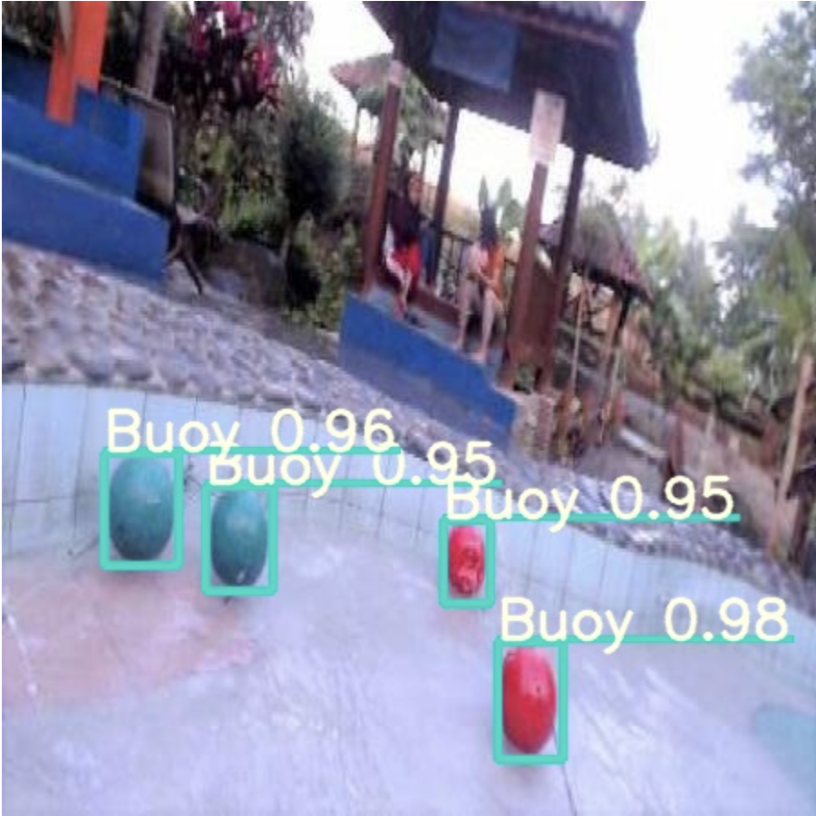
The other two images shown are evidence of the model’s sucessful training, as it is able to recognize buoys from photos the model was not trained with
Simulation Testing Using Gazebo
November 2023


This year, we set up a simulation to test our ASV. The simulation sped up development time as it became easier and quicker to test new features. Additionally, the ability to test in simulation supplements the limitations of testing outdoors in the cold winter months. The simulation is run in Gazebo, a robotics simulator designed to work with ROS. The ArduPilot firmware is used on our flight controller, which is reflected in the simulation. Using ArduPilot with Gazebo proved to be slightly trickier than anticipated, as most of the resources available online used PX4 instead of ArduPilot. Tutorials from Intelligent Quads that used ArduPilot in their simulations proved to be a very valuable resource to learn about ArduPilot, and the software team was able to create simulation using the Intelligent Quads tutorial as a reference.
Dependencies for the Simulation
Gazebo - A 3D robotics simulator
ArduPilot - ArduPilot is a flight controller firmware that controls the boat’s movement.
ArduPilot provides the boat with positional data and can move the boat with velocity or positional setpoints in the simulation.
To run ArduPilot in Gazebo, a Gazebo ArduPilot plugin had to be installed.
MAVProxy - a command-line ground station software.
MAVProxy can be used to send waypoint missions to the boat.
ArduPilot does not have a GUI, so MAVProxy is used with the simulation to set the driving mode of the boat and can send positions or velocities to ArduPilot through MAVProxy.
MAVLink - a communication protocol used by MAVProxy uses.
MAVProxy communicates with ArduPilot by sending and receiving MAVLink packets.
Mavros - enables communication between ROS and ArduPilot.
Desired setpoints are published in ROS to mavros topics
Mavros thenconverts to MAVLink commands that communicate with ArduPilot.
Gazebo Models
Installing buoyancy plugins for our boat and markers in Gazebo was another key part of developing our simulation environment. Our Gazebo world has water, so unless our boat model had buoyancy, it would sink! We pulled the usv_dynamics_plugin from the PX4 SITL repository and could build the plugin independatly from the PX4 repository. The plugin could then be used in any Gazebo models that needed to float. To further support our testing environment, we created several buoy models with our buoyancy plugin to replicate navigation tasks that the boat will have to execute in real life at the RoboBoat competition.
While setting up buoyancy for models, we also tried to set up a world and model for a car. Using a car instead of a boat would simplify our simulation as we would not need to worry about the physics of floating objects. It also removed the effect of momentum. When we stop sending waypoints to the boat, it can be difficult to tell if ArduPilot has actually stopped sending positions and it is just drifting due to momentum from the previously sent position, or if ArduPilot is still sending goal positions to the boat and the drifting is actually undesired movement. The car eliminates this uncertainty because the wheels simply stop spinning when ArduPilot stops sending positions to it, and it stops immediately. The model of the car used in our simulation is the Clearpath Robotics Husky. Currently, our sim supports a boat and a car, and we use them interchangeably depending on the software we are testing.
Using the Simulation
To run the simulation, we have to launch Mavros, MAVProxy, and the simulation world in Gazebo. We can set the boat or car to Guided mode with MAVProxy, and then run our code to drive the vehicle.
Design Philosophies: Stability, Maneuverability, Reliability
October 2023


Iceberg ASVs new design still aligns with their iterative approach to the project overall. At a base level, the ASV concept remains the same: pontoon hulls with a supporting bridge. However, the design team have made strategic changes to improve the ASV for the 2024 season. The design will have a similar pontoon to the previous year’s design, but slightly more ‘full’ to improve stability. The choice to increase size was to allow for more deck space and real estate for hardware and sensors. The length of the boat has increased by 1.5 and other parameters (including width and depth) were increased by 1.25. It is important to note that the size increase was kept relatively tame as the design team did not want to ramp up the resistance on the hulls. For instance; the bigger the boat, the more water to move out of the way, which results in less maneuverability.
The design team also plans to use fiberglass this year. In the previous year, the design team only used Flex Seal. The use of fiberglass will smooth out our hulls and decrease the resistance they encounter moving through the water.
The thruster configuration is the same as the previous year because it proved to be reliable. The boat was maneuvering well overall in testing, and at the competition itself.
Finally, the modularity of Iceberg ASVs boat design is crucial. As the boat is being shipped a long distance, the boat can be broken down into its components — hulls, bridge, thrusters, boxes, and sensor mounts. This also allows for relatively simple repairs in the case anything could happen to the ASV.
Electrical System Upgrades
October 2023
After attending the 2023 RoboNation RoboBoat competition, the electrical team determined there were some physical and electrical changes that needed to be implemented.
Physical Changes
Working with the design team, the electrical team has implemented two electrical houses situated next to one another. The smaller box (13.8 x 9.8 x 5.9) will contain two batteries — one battery is to provide power to all components contained in the other electrical box, and the other is to provide power to the Jetson TX2. The larger electrical box (17.7 x 13.8 x 7.9) will contain all other electrical components.
In the previous electrical housing design, the physical kill switch was secured using command strips. For the new electrical house, a 3D printed mount will be placed between the two houses to hold the physical kill switch. Continuing, a screw-in waterproof USB connector will be situated in the smaller electrical box and will be used for the Jetson TX2 USB connection.
Previously, the electrical team used velcro strips to secure the electrical wire. This was not ideal as the team was constantly rearranging components, making the velcro become loose which made it confusing to debug. In the new electrical housing design, the electrical team implemented DIN rails in place of velcro. The decision behind the DIN rails was because they are popular in the industry for affordable prices, as well as providing a simple way to reorganize the structure.
Electrical Changes
In addition to the physical changes to the structure the Iceberg ASV team has made some improvements to the reliability of the remote kill switch.
Firstly, the Iceberg ASV team will be using DIN rail terminals instead of a bus bar for a more secure and clean electrical connection. This will also aid in debugging, as well as overall general safety.
In regards to the remote kill switch, the remote controller will send pulse width modulated (PWM) signals to the receiver. From here, the receiver will output the same PWM signals that the controller sends out. Then, the receiver can be used to control the remote kill switch.
To control the power to the motors, a circuit will be designed that will convert the PWM signal from the receiver to a DC signal to a relay that controls the power going to the motors. Therefore, the motors can be de-energized, but still keep the remaining systems on for the boat. This satisfies the safety requirements for the competition.
Although the electrical team has determined and are working diligently to implement core changes, there are still some items that may potentially be added and executed. This includes implementing a battery monitor to increase safety precautions, and adding more status LEDs to aid in debugging.
Communication System: Hardware Overview
September 2023


What kind of hardware does our ASV use and how do they work together? This article provides a breakdown of each hardware component used in the ASV’s communication system
NVIDIA Jetson Tx2
This is the main computer. It is an embedded GPU module. It is used to run all of the startup scripts, run the ROS code, perform logging, and for on-shore communication. The LiDAR and camera plug into the Jetson.
Pixhawk
This is the flight controller. The Pixhawk with the ArduPilot firmware (Px4 is the other common option) has been flashed. The GPS, IMU, and RC receiver plug into the Pixhawk. The Jetson Tx2 sends the Pixhawk commands for sending the boat to a specific GPS waypoint or sets a specific velocity, and the Pixhawk handles the motor mixing to send the boat to the specified waypoint or sets it to the desired velocity by sending a signal to the ESCs. The Pixkawk has to be configured by the software team, but the low-level motor mixing does not.
Electronic Speed Controller (ESC)
These convert a signal from the Pixhawk to a PWM signal used by the thrusters to control the boat's movement. They are also used to power the thrusters. Iceberg ASV uses two Blue Robotics T200 thrusters in a stationary orientation and steer with differential thrust.
Remote Control (RC) Receiver
The RC receiver picks up the signal from our remote control, allowing the team to manually steer the boat from shore.
Global Positioning System (GPS)
The GPS receiver provides the Pixhawk with positional data. This allows the Pixhawk to know where the boat is and know when it has reached a target waypoint. The GPS cannot operate accurately indoors - any location inside creates a form of ‘Faraday Box’ which prevents communication signals from entering or exiting. This is why outdoor testing is so important!
Inertial Measurement Unit (IMU)
The IMU provides positional data similar to a GPS. It also provides 9 degrees of motion, giving yaw, pitch, and roll, and a compass. There is an IMU built into the Pixhawk, and there is also a higher-quality external one that plugs into the Pixhawk. The IMU is used in addition to the GPS because it's much faster than the GPS; however, it becomes inaccurate after a while, so the GPS continually corrects it. For example, the team could get a GPS reading once every 10 seconds and 5 IMU readings every second. The IMU fills in the gaps between GPS readings, and as it's corrected by the GPS every 10 seconds, there is not enough time for any significant inaccuracies to occur.
LiDAR - Light Detection and Ranging
A LiDAR is a distance scanner. Iceberg ASVs is 2D — meaning it measures distances in a horizontal plane. It has a range of 30 m in 270°. It could take 1081 measurements within a single scan and perform a number of scans per second. It provides an array of distances for each scan. If the LiDAR picks up no obstacle within the 30m range, the distance is "inf". The data can them be used to determine how close objects are and where they are relative to the boat.
Figure 1.1: LiDAR scan example
Intel RealSense Depth Camera D435
The RealSense Depth Camera provides us with a video feed and depth maps. The depth sensor in the camera does not work very well outdoors because it uses an infrared sensor and has a limited range so we are not currently using it. The Iceberg ASV team is just using the regular RGB camera. They run object detection algorithms on camera frames to identify objects and locate the object's location within the frame to determine the general direction that the object lies in.