

2025 - 2026
Iceberg ASV will be returning to the International RoboBoat competition in February 2026, to represent Newfoundland & Labrador and Canada.
Check out our blog below to see what we’ve been up to!
Articles:
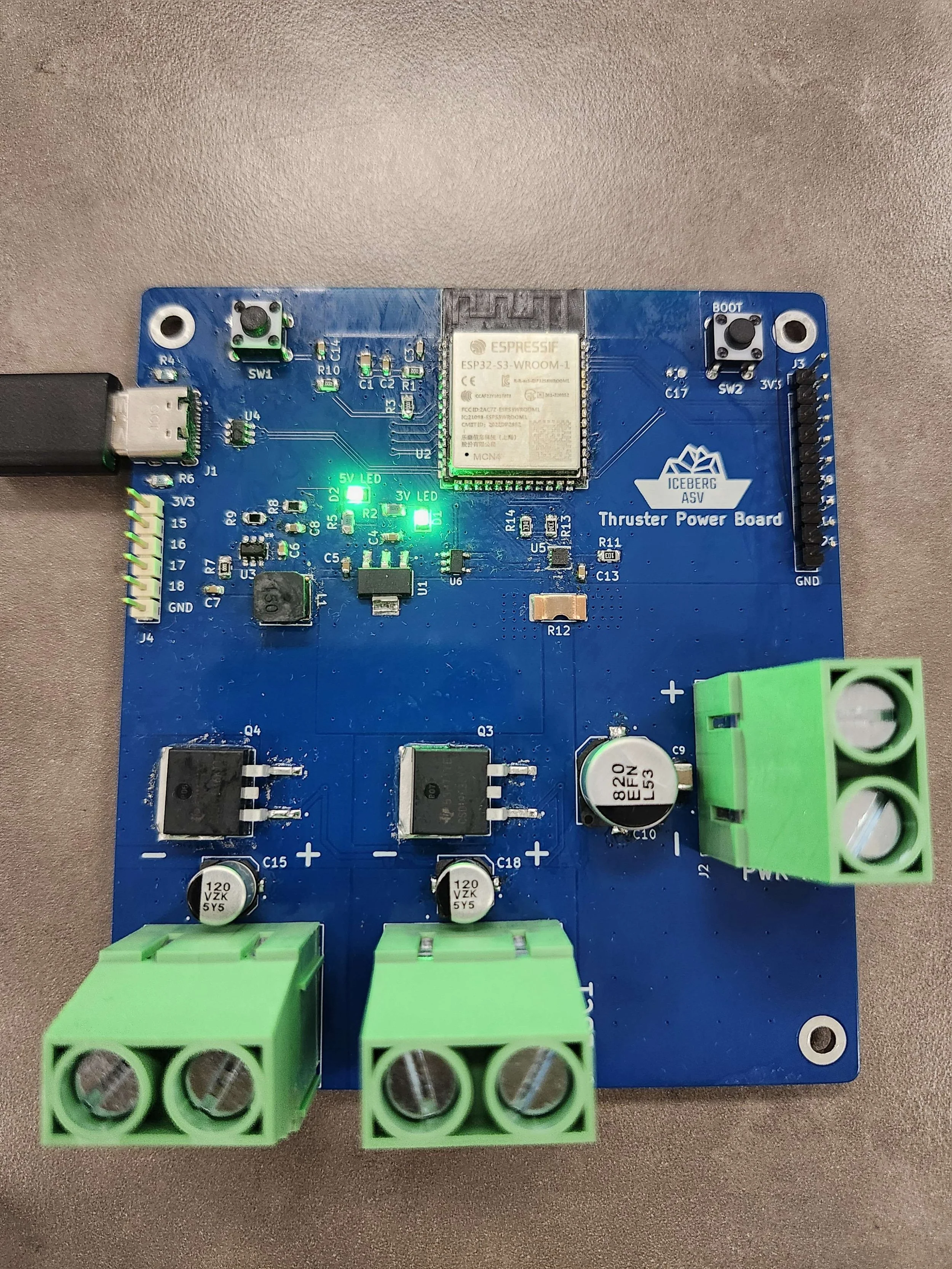
Our New Thruster Power Board Design
Our ASV’s Kill Switch Board Gets An Upgrade
Designing a Status LED Tower Control Board

Our New Thruster Power Board Design
By Harry Ngo
2025 - 2026 Blog:
November 2025
This year, the Iceberg ASV team designed a custom Printed Circuit Board (PCB) to improve the vessel’s power system management. The thruster power board accepts a 14.8 V supply from one of the lithium-polymer batteries used to power the ASV. The board incorporates four N-channel MOSFETs connected in parallel, enabling the safe and controlled operation of two electronic speed controllers (ESCs) with a combined current draw of up to 50 A.
An onboard ESP32 microcontroller is used to generate control signals for switching the N-channel MOSFETs and regulating power delivery to the dual ESCs. The ESC output connectors are equipped with flyback diodes to protect the circuit from high-voltage transients caused by inductive loads. Overcurrent protection is implemented using a high-speed current-sense amplifier with an integrated comparator, which monitors current through a sense resistor.
A USB-C port with electrostatic discharge (ESD) protection allows the ESP32 firmware to be programmed directly from a USB-connected laptop. Additional spare connector headers are included to facilitate software testing and debugging during development.
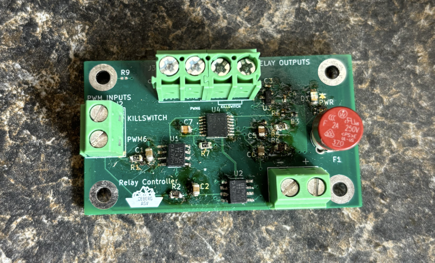
Our ASV’s Kill Switch Board Gets An Upgrade
By Katie Yanchus

August 2025
How The Boards Works:
Our ASV features a remote-controlled Emergency Stop (E-Stop) switch for safety. The FlySky FS-i6 controller sends Pulse Width Modulation (PWM) signals to a custom PCB that converts the signal into a proportional direct current (DC) voltage. This conversion is necessary to control a 12V relay that powers the thrusters. The PCB uses an operational amplifier to process the PWM signal, and a voltage comparator compares the resulting DC voltage to a reference voltage. If the voltage drops below the threshold, the relay opens, cutting power to the thrusters and ensuring the ASV can be safely stopped. For a more in-depth description of the circuit operation, see our blog post from the first revision of this board: here!
What We Improved:
Since this PCB’s creation there were several improvements identified and the team decided to respin the PCB in preparation for RoboBoat 2026. A fuse was added to the PCB as a safety feature to protect the system from short circuits and potential damage. An LED was also included to help with debugging by indicating whether the board was receiving power. Additionally, the team chose to replace the original push-button terminal blocks with screw terminal blocks, which had proven easier to work with in other parts of the system. A previously missing trace on the 12V rail, a detail missed during prior fabrication, has now been fixed as well. Finally, for a personal touch, the updated board now features the Iceberg ASV logo on the silkscreen!
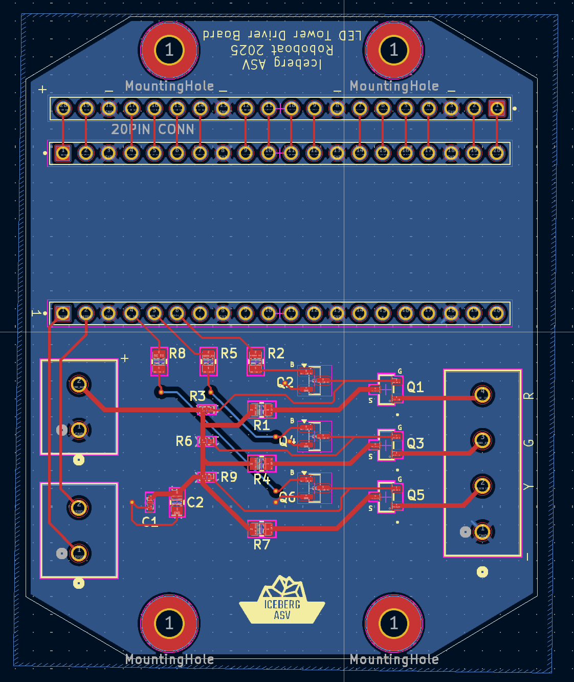
Designing a Status LED Tower Control Board
By Cameron Taveroff
June 2025
As part of this year’s Iceberg ASV upgrades, the team designed a custom LED tower control board to manage the vessel’s status and navigation lights. The goal of this board was to provide reliable, software-controlled lighting to indicate the status of our system, that being either in RC, autonomous, or E-Stop mode.
The LED tower board uses a combination of NPN BJTs and P-channel MOSFETs to switch multiple LED arrays safely and efficiently. The BJTs are used as low-side drivers for the PMOS' which act as high-side switches. Due to the configuration of the LED tower and additional design constraints, high-side switching was required whereas low-side switching is typically preferable. Base and gate resistors were carefully selected to ensure proper operation and minimize power loss while being fully compatible with 3.3V logic signals from the microcontroller.
To protect the board and the LEDs, current-limiting resistors were included in the design, protecting the transistors from voltage spikes and ensuring stable operation. The board also includes spare headers and test points to simplify debugging and software development in the future.